 |
SPEED
|
 |
SPEED
|
The tutorial folder can be downloaded from here. and contains different examples of elastic wave problems solved with SPEED. The meshes for the following examples have been created using the CUBIT software. See Input files generation for the mesh generation of the following test cases.
Physical problem: plane wave propagation
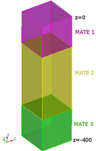
The folder PLANE_WAVE/1_TEST_SEM contains:
test1_conf_sem.mesh: Mesh constitute by 40 hexahedral elements (12 for MATE 1, 24 for MATE 2 and 4 for MATE 3) 1 1 hex 1 2 3 4 5 6 7 8 2 1 hex 2 9 10 3 6 11 12 7 3 1 hex 4 3 13 14 8 7 15 16 4 1 hex 3 10 17 13 7 12 18 15 5 1 hex 5 6 7 8 19 20 21 22 6 1 hex 6 11 12 7 20 23 24 21 7 1 hex 8 7 15 16 22 21 25 26 8 1 hex 7 12 18 15 21 24 27 25 9 1 hex 19 20 21 22 28 29 30 31 10 1 hex 20 23 24 21 29 32 33 30 11 1 hex 22 21 25 26 31 30 34 35 12 1 hex 21 24 27 25 30 33 36 34 13 2 hex 35 31 30 34 37 38 39 40 14 2 hex 31 28 29 30 38 41 42 39 15 2 hex 34 30 33 36 40 39 43 44 16 2 hex 30 29 32 33 39 42 45 43 17 2 hex 37 38 39 40 46 47 48 49 18 2 hex 38 41 42 39 47 50 51 48 19 2 hex 40 39 43 44 49 48 52 53 20 2 hex 39 42 45 43 48 51 54 52 ...and 84 boundary faces (4 for absorbing boundary conditions and 80 for Dirichelt boundary conditions)
1  4  quad  98  94  93  97
2  4  quad  94  91  92  93
3  4  quad  97  93  96  99
4  4  quad  93  92  95  96
5  5  quad  99  96  83  86
6  5  quad  96  95  82  83
7  5  quad  86  83  74  77
8  5  quad  83  82  73  74
9  5  quad  77  74  65  68
10  5  quad  74  73  64  65
...
test1_conf_sem.mate: Description of mechanical properties for MATE 1,2 and 3, id degree rho vs vp qs qp MATE 1 4 1800 300 600 30 60 MATE 2 4 2200 2000 4000 200 400 MATE 3 4 2200 2000 4000 200 400absorbing and Dirichelet boundary conditions
ABSO 4
DIRY 5 8 0.0 0.0 0.0 0.0
DIRZ 5 8 0.0 0.0 0.0 0.0
FUNC 8 0 0.0
and plane wave forcing term
PLAX 9 3 1.0
FUNC 9 4 9.8696 2.0
LS.input. File containing physical coordinates of monitored point. 4 01 50 50 0 02 50 50 -150 03 50 50 -250 04 50 50 -300
SPEED.input: header fileFILES_MPI: folder containing *.mpi files, created after partitoning.MONITORS: folder containing output files.run_speed.sh: example of script file for the execution of SPEED on your machine (to be modified according to your installation path). To run SPEED open a terminal, go to "1_TEST_SEM" and digit the command ./run_speed.sh
The folder PLANE_WAVE/2_TEST_SEM_NLE contains:
test1_conf_sem.mesh: see description in Test SEmtest1_conf_sem_nle.mate: Description of mechanical properties for MATE 1,2 and 3, id degree rho vs vp qs qp MATE 1 4 1800 300 600 30 60 MATE 2 4 2200 2000 4000 200 400 MATE 3 4 2200 2000 4000 200 400absorbing and Dirichelet boundary conditions
ABSO 4
DIRY 5 8 0.0 0.0 0.0 0.0
DIRZ 5 8 0.0 0.0 0.0 0.0
FUNC 8 0 0.0
plane wave forcing term
PLAX 9 3 1.0
FUNC 9 4 9.8696 2.0
and non-linear curve for G/G0 and damping
MATN   1   4   11  50
FPEK 0.67
  Modulus curve
FUNC 11 60 25   0.000001000   1.000000000  0.000001873   0.999999000  0.000003769   0.998883000  0.000007040   0.998883000  0.000010000   0.985000000  0.000022461   0.955000000  0.000040120   0.928000000  0.000068536   0.860000000  0.000093665   0.825000000  0.000100000   0.800000000  0.000172359   0.700000000  0.000206041   0.650000000  0.000273333   0.600000000  0.000362603   0.520000000  0.000488237   0.450000000  0.000638131   0.370000000  0.000797643   0.320000000  0.001000000   0.280000000  0.001139850   0.260000000  0.001403740   0.230000000  0.002000000   0.190000000  0.003000000   0.150000000  0.007000000   0.105000000  0.007500000   0.104000000  0.010000000   0.100000000
  Damping curve
FUNC 11 61 25   0.000001000   0.015000000  0.000001873   0.015100000  0.000003769   0.015200000  0.000007040   0.015300000  0.000010000   0.015400000  0.000022461   0.015500000  0.000040120   0.018000000  0.000068536   0.024000000  0.000093665   0.027000000  0.000100000   0.029000000  0.000172359   0.037000000  0.000206041   0.040000000  0.000273333   0.047000000  0.000362603   0.055000000  0.000488237   0.067000000  0.000638131   0.075000000  0.000797643   0.090000000  0.001000000   0.100000000  0.001139850   0.105000000  0.001403740   0.120000000  0.002000000   0.140000000  0.003000000   0.160000000  0.007000000   0.195000000  0.007500000   0.200000000  0.010000000   0.220000000
SPEED.input, FILES_MPI, MONITORS: see description in Test SEmrun_speed.sh: example of script file for the execution of SPEED on your machine (to be modified according to your installation path). To run SPEED open a terminal, go to "2_TEST_SEM_NLE" and digit the command ./run_speed.sh
The folder PLANE_WAVE/INPUTS/3_TEST_SEM_NH contains:
test1_conf_sem.mesh: see description in Test SEmtest1_conf_sem_nle.mate: Description of mechanical properties for MATE 1,2 and 3, id degree rho vs vp qs qp MATE 1 4 2200 2000 4000 200 400 MATE 2 4 2200 2000 4000 200 400 MATE 3 4 2200 2000 4000 200 400absorbing and Dirichelet boundary conditions
ABSO 4
DIRY 5 8 0.0 0.0 0.0 0.0
DIRZ 5 8 0.0 0.0 0.0 0.0
FUNC 8 0 0.0
plane wave forcing term
PLAX 9 3 1.0
FUNC 9 4 9.8696 2.0
and case description for not-honoring technique
CASE 99 1 10
SPEED.input, FILES_MPI, MONITORS: see description in Test SEmALL.out: triangular mesh describing the bottom surface from which the not-honoring method is appliedXYZ.out: triangular mesh describing the top surface to which the not-honoring method is appliedrun_speed.sh: example of script file for the execution of SPEED on your machine (to be modified according to your installation path). To run SPEED open a terminal, go to "3_TEST_SEM_NH" and digit the command ./run_speed.sh
The folder PLANE_WAVE/4_TEST_DG contains:
test1_nnconf_dg.mesh: Mesh constitute by 124 hexahedra elements (96 for MATE 1, 24 for MATE 2 and 4 for MATE 3) 1 1 hex 1 2 3 4 5 6 7 8 2 1 hex 2 9 10 3 6 11 12 7 3 1 hex 9 13 14 10 11 15 16 12 4 1 hex 13 17 18 14 15 19 20 16 5 1 hex 4 3 21 22 8 7 23 24 6 1 hex 3 10 25 21 7 12 26 23 7 1 hex 10 14 27 25 12 16 28 26 8 1 hex 14 18 29 27 16 20 30 28 9 1 hex 22 21 31 32 24 23 33 34 10 1 hex 21 25 35 31 23 26 36 33 ...and 184 boundary faces (4 for absorbing condition, 28 for DG interface conditions and 152 for Dirichelt boundary conditions )
1  4  quad  254  246  245  253
2  4  quad  246  243  244  245
3  4  quad  253  245  250  256
4  4  quad  245  244  249  250
5  5  quad  256  250  248  255
6  5  quad  250  249  247  248
7  5  quad  234  231  222  225
8  5  quad  231  230  221  222
9  5  quad  225  222  213  216
10  5  quad  222  221  212  213
...
test1_nnconf_dg.mate: Description of mechanical properties for MATE 1,2 and 3 id degree rho vs vp qs qp MATE 1 4 1800 300 600 30 60 MATE 2 4 2200 2000 4000 200 400 MATE 3 4 2200 2000 4000 200 400absorbing and Dirichelet boundary conditions
ABSO 4
DIRY 5 8 0.0 0.0 0.0 0.0
DIRZ 5 8 0.0 0.0 0.0 0.0
FUNC 8 0 0.0
DG interface conditions
DGIC 6  1
DGIC 7  0
DGIC 8  1
DGIC 9  0
and plane wave forcing term
PLAX 9 3 1.0
FUNC 9 4 9.8696 2.0
LS.input. File containing physical coordinates of monitored point. 4 01 50 50 0 02 50 50 -150 03 50 50 -250 04 50 50 -300
SPEED.input: header fileFILES_MPI: folder containing *.mpi files, created after partitoning.MONITORS: folder containing output files.run_speed.sh: example of script file for the execution of SPEED on your machine (to be modified according to your installation path). To run SPEED open a terminal, go inside the "4_TEST_DG" folder and digit the command ./run_speed.sh
The post-processing and visualization of the results is obtained through MATLAB scripts, provided in the folder POST-PROC inside each test case folder.
REWRITE_MONITOR_FORMAT.m to rewrite the output files (from MONITORXXXXXX.D to monitorxxxxxx.d) stored in the directory MONITORS. PLOT_MONITOR.m to plot the output results.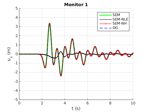
.
Physical problem: Point source wave propagation
Benchmark tectcase Layer over a half space (LOH1) described in:
"Day S.M., Bradley C.R. 2001. Memory-efficient simulation of anelastic wave
propagation. Bulletin of the Seismological Society of America, 91(3): 520–531."
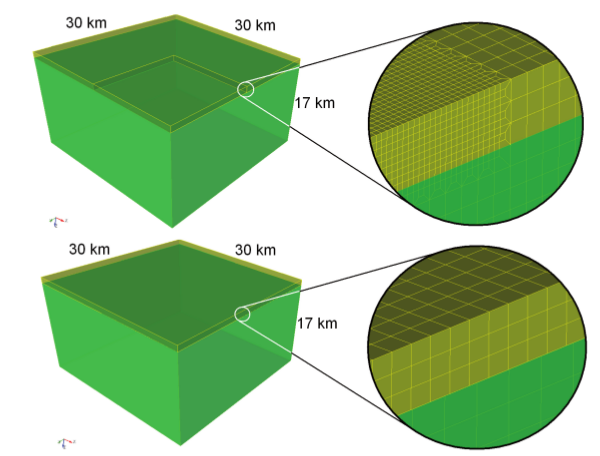
Physical problem: Plane wave propagation
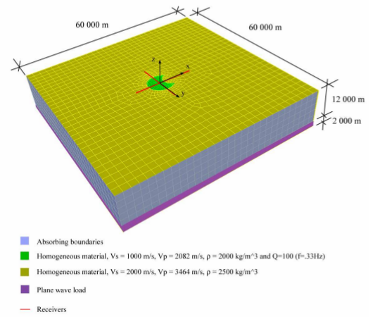
Benchmark tectcase proposed by F.J. Sanchez-Sesma, F. Luzon 1995. Seismic Response of a Three-Dimensional Alluvial Valleys for Incident P, S and Rayleigh Waves. Bulletin of the Seismological Society of America, 85, 890-899. See also:
The folder CROISSANT_VALLEY contains the following subdirectories:
.
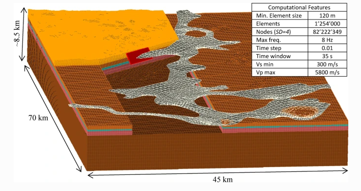
Physical problem: Finite fault source for Mw 4.9 earthquake
Case study analysed in: Smerzini, C., Vanini, M., Paolucci, R. et al. Regional physics-based simulation of ground motion within the Rhȏne Valley, France, during the MW 4.9 2019 Le Teil earthquake. Bull Earthquake Eng (2022).
.